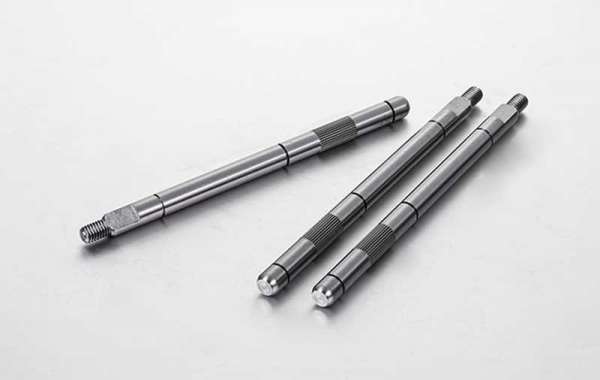
In mechanical engineering, an axisymmetric object that is specially designed to transfer power is known as a drive shaft.
Shafts are used to support immobile, oscillating or rotational parts of machines, but they do not transfer any angular momentum and are therefore subject to flexion.
Likewise, a drive shaft is a shaft that transfers torque and is subject to torsional loads. This is the result of the transmission of a couple and it may at the same time be subject to other types of mechanical stress.
The typical shaft layout is a stepped element with a circular cross-section, with a wider cross-section at the center so that several elements can be mounted on it at its ends, which results in a greater section modulus at the central area where flexion causes greater loads.
Shafts have to be as short as possible in order to avoid high bending stress. To that same end, support bearings should be placed as close as possible to high loads.
Try to avoid a stress concentration by using generous fillet radii in section changes.
In order to prevent vibration issues, fast-turning shafts require a good dynamic balance, good fastening at the supports and a rigid configuration.
Hollow shafts perform better in regard to vibrations, though they are more expensive to manufacture and have a greater diameter.
Rigidity is usually the most critical factor when designing shafts, and steel is used in order to prevent it.
Ningbo Shitai Precision Machinery Co., Ltd. is not only a drive shaft supplier but also a linear shaft factory. Welcome to visit our official website.


