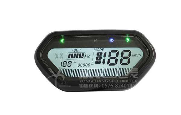
The input signal of the pulsar speedometer coil is a relatively constant voltage value, generally the power supply voltage is directly added to the coil or assigned to it through the network with a constant voltage value. Therefore, the loop current mainly depends on the coil impedance and generally does not involve other loop components. In order to minimize its shunting effect on other branches, generally the wire is thin, the number of turns is large, the inductance and resistance are large, and the coil current is not large.
The pulsar speedometer is activated when the power supply voltage of the pulsar speed meter is lower than the rated voltage of the coil. The reason for the malfunction of the overcurrent pulsar speedometer is that the micro switch in the pulsar speedometer is damaged.
After the pulsar speedometer starts normally, the pulsar speedometer automatically cuts off the power loop to ensure the normal low-power operation of the pulsar speedometer. When AC 220V, ensure that the contact is reliable and does not operate. The conductive terminals of the lcd speedometer are connected together, and between the exposed non-charged metal parts or shells, it can withstand an AC voltage of 2000V (effective value) 50Hz for 1 minute without insulation breakdown or flashover.
If you want to purchase electric vehicle speedometer, welcome to send us messages!


