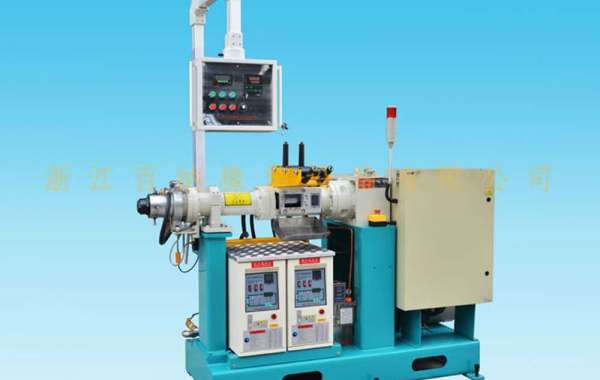
- Hopper cylinder – The rubber extruder machine is made of cast steel and is jacketed for water-cooling. The insides are made wear resistant by chrome plating or nitrited alloy steel. The insides also have spiral undercuts for high feeding efficiency.
- Rollfeeder – The feed roll is operated by the screw by the means of a gear and pinion. The feed roll surface is hardened and an inside chamber for tempering fluid is provided.
- Forward cylinder – The cylinder is made of nitrited alloy steel (for high wear resistance) and peripheral drilling for circulating tempering fluid is provided. Sometimes, bi – metallic linings are given. The pins are made of high grade alloy steel hardened fro greater wear resistance.
- Screws – The twin screws are made of cast steel and are chrome plated. They are usually bored for cooling. The diameter of normal screws is 60 – 200 mm with a length of 5 – 20 times the diameter. The functions of the screw are manifold – mixing, blending, homogenizing, dispersing, compounding, degassing. Twin screw extruders are the most commonly used extruders. They can either be intermeshing or nonintermeshing. Nonintermeshing extruders behave like two single screw extruders with only minor interactions between the two screws. Another classification is the direction of rotation of screws. Co – rotating screws have both screws rotating in the same direction and the material exchanges from screw to screw. On the other hand, the counter – rotating screws have material transported through the extruder in a figure eight channel.
- Feeding screws – They are made of high alloy steel and polished, nitrited or satellite on their tips. They are also drilled for tempering fluid circulation.
- Dies – Many special arrangements of extruder dies are used for composite layered sheets. Two types of rubber enter the die from two extruder barrels and exit as one sheet. The top and bottom layers are of different materials.
- The mixing chamber – The chamber which contains the screws and where the actual mixing takes place. This region is the region of maximum power consumption as well as maximum temperature rise. The throughput of an extruder is typically ~ 400 kg/hr.
- Vacuum zone – A vacuum zone inside the cylinder is created by the use of screws with high thread height. This is done to vent the rubber from inclusions of gases to eliminate porosity.
- Extruder tempering system – Usually it is a closed circuit type with electrical heating. Both single – and twin – screw extruders may use hot oil circulation systems for temperature regulation. The sump temperature is set to 204 degrees, and the extruder barrel is heated or cooled depending upon internal heat generation. Circulation may be constant (no temperature controllers) or may be adjusted to control individual zone temperatures.
- Gear reducer – The screw speed varies normally from 30 – 60 rpm. The gear reducer reduces the motor speed to this speed. They are usually provided with forced feed lubrication system.
- Thrust bearings – They form an integral part of the extruder system. Optimized design for long life at the maximum extrusion pressure and screw speed.
We wholesale rubber vulcanizing machine and welcome to your come and purchase!


