Thermoplastics are characterized by expansion after heating and contraction after cooling. Of course, the volume will shrink after pressurization. In the injection molding process, the molten plastic is first injected into the mold cavity. After the filling is completed, the molten material cools and solidifies. When the plastic part is taken out of the Bucket Mould Manufacturer, shrinkage occurs. This shrinkage is called forming shrinkage. During the period from when the mold is taken out to stabilize the plastic part, there will still be slight changes in size. One change is to continue to shrink. This shrinkage is called post-shrinkage.
Another change is that some hygroscopic plastics swell due to moisture absorption. For example, when the water content of nylon 610 is 3%, the size increase is 2%; when the water content of glass fiber reinforced nylon 66 is 40%, the size increase is 0.3%. But the main role is forming shrinkage.
At present, the method of determining the shrinkage rate of various plastics (forming shrinkage + post shrinkage) generally recommends the provisions of DIN16901 in the German national standard. That is, the difference between the size of the mold cavity at 23°C±0.1°C and the size of the corresponding plastic part measured at a temperature of 23°C and a relative humidity of 50±5% after being placed for 24 hours after forming is calculated.
The shrinkage rate S is expressed by the following formula: S={(D-M)/D}×100%(1)
Among them: S-shrinkage rate; D-mold size; M-plastic part size.
If the mold cavity is calculated according to the known plastic part size and material shrinkage rate, it is D=M/(1-S). In order to simplify the calculation in the mold design, the following formula is generally used to find the mold size:
D=M+MS(2)
If a more accurate calculation is required, the following formula shall be applied: D=M+MS+MS2(3)
However, when determining the shrinkage rate, because the actual shrinkage rate is affected by many factors, only approximate values can be used. Therefore, the calculation of the cavity size by formula (2) basically meets the requirements. When manufacturing the mold, the cavity is processed according to the lower deviation, and the core is processed according to the upper deviation, so that it can be properly trimmed if necessary.
The main reason why it is difficult to accurately determine the shrinkage rate is firstly because the shrinkage rate of various plastics is not a fixed value, but a range. Because the shrinkage rate of the same material produced in different factories is not the same, even the shrinkage rate of the same material with different batch numbers produced in one factory is different.
Therefore, each factory can only provide users with the shrinkage rate range of the plastic produced by the factory. Secondly, the actual shrinkage during the forming process is also affected by factors such as the shape of the plastic part, mold structure and forming conditions.
Plastic part shape
For the wall thickness of the formed part, the cooling time of the thick wall is generally longer, so the shrinkage rate is also larger. For general plastic parts, when the size of the melt flow direction L is different from the size perpendicular to the melt flow direction W, the difference in shrinkage is also greater. From the point of view of the melt flow distance, the pressure loss of the part far from the gate is large, so the shrinkage rate at this point is also larger than that of the nearest gate. Because shapes such as ribs, holes, bosses, and carvings have shrinkage resistance, the shrinkage rate of these parts is small.
Mould structure
The gate type also has an effect on the shrinkage rate. When using a small gate, the shrinkage rate of the plastic part increases because the gate solidifies before the end of the holding pressure. The cooling circuit structure in the injection mold is also a key in the mold design. Inappropriate design of the cooling circuit will result in poor shrinkage due to the uneven temperature throughout the plastic parts, which will result in out of tolerance or deformation of the plastic parts. In the thin-walled part, the influence of mold temperature distribution on shrinkage is more obvious.
Mold size and manufacturing tolerances
In addition to calculating the basic dimensions of the mold cavity and core through the formula D=M(1+S), there is also a problem of machining tolerances. By convention, the machining tolerance of the mold is 1/3 of the tolerance of the plastic part. However, due to differences in plastic shrinkage range and stability, first of all, the dimensional tolerances of plastic parts formed by different plastics must be rationally determined. That is to say, the dimensional tolerance of plastic molded plastic parts should be larger due to the larger shrinkage rate range or the poorer shrinkage rate stability. Otherwise, a large number of waste products with out-of-poor dimensions may occur.
For this reason, various countries have specially formulated national standards or industry standards for the dimensional tolerances of plastic parts. China has also established ministerial professional standards. But most of them have no corresponding dimensional tolerances of the mold cavity. The German national standard has specially formulated the DIN16901 standard for plastic part dimensional tolerances and the corresponding DIN16749 standard for mold cavity dimensional tolerances. This standard has a greater impact in the world, so it can be used as a reference for the plastic mold industry.
About the dimensional tolerance and allowable deviation of plastic parts
In order to reasonably determine the dimensional tolerances of plastic parts formed by materials with different shrinkage characteristics, let the standard introduce the concept of forming shrinkage difference △VS.
△VS=VSR_VST(4)
Where: VS-forming shrinkage difference VSR-forming shrinkage rate in the direction of melt flow VST-forming shrinkage rate in the direction perpendicular to the melt flow.
According to the plastic △VS value, the shrinkage characteristics of various plastics are divided into 4 groups. The group with the smallest △VS value is the high-precision group, and so on, the group with the largest △VS value is the low-precision group. And according to the basic dimensions, the precision technology, 110, 120, 130, 140, 150 and 160 tolerance groups have been compiled. It is also stipulated that the dimensional tolerances of plastic parts with the most stable shrinkage characteristics can be selected from 110, 120 and 130 groups.
The dimensional tolerances of plastic molded parts with moderately stable shrinkage characteristics are 120, 130, and 140. If 110 groups of dimensional tolerances are used to form plastic parts with this type of plastic, a large number of out-of-size plastic parts may be produced. The dimensional tolerances of plastic parts with poor shrinkage characteristics are selected from groups 130, 140 and 150.
The dimensional tolerances of plastic parts with the worst shrinkage characteristics are selected from groups of 140, 150 and 160. When using this tolerance table, you need to pay attention to the following points. The general tolerances in the table are used for dimensional tolerances that do not indicate tolerances.
The tolerance for marking the deviation directly is the tolerance zone used for marking the tolerance of the plastic part. The upper and lower deviations can be determined by the designer. For example, if the tolerance zone is 0.8mm, the following upper and lower deviations can be selected. 0.0; -0.8; ±0.4; -0.2; -0.5 and so on. Each tolerance group has two sets of tolerance values A and B. Among them, A is the size formed by the combination of mold parts, which increases the error caused by the misalignment of the mold parts.
This increase is 0.2mm. Where B is the size directly determined by the mold parts. Precision technology is a set of tolerance values specially set up for plastic parts with high precision requirements. Before using the tolerances of plastic parts, we must first know which tolerance groups are suitable for the plastic used.
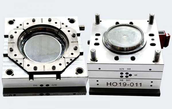
We are a professional molding company, sell different design of mold, 18L Pail Mould is one of them,welcome to visit our website.